Slice parameters
The list of changes is as follows.
- Printer tab added
“General-Temperature” , “Cooling-Reset Temperature At Heights” have been moved to “Printer”.
“Temperature Control List” and “Control Module” are added. - General
Added “Speed”-“First Layer Maximum Speed” and “First Layer Maximum Travel Speed”.
Added “Retraction”-“Extrude Speed” and “Extra Restart Length”. - Shells(Ver4.6 Perimeter)
Added “Speed”-“Visible Interior Max Speed” and “Invisible Interior Max Speed”. - Infill
Added “Strength Infill”-“Infill Density Control”. - Raft
Added “Middle Layers”-“Path Width” and “Fill Density”.
Added “Top Layers”-“Path Width”. - Additions
Added “Brim”-“Generate Brim Inside Holes”. - Cooling
Added “Back Fan Speed”. - Advanced
Added “Ironing”. - Others
Added “Z Offset”.
The method of specifying pause has been changed from height specification to layer number specification.
Temperature Control List Control Module
The check box of the “Temperature Control List” determines whether or not the “Control Module” can be operated.
The items that can be set in “Control Module” have been partially changed from Ver4.6.
First, the control range was changed from mm to layer-layer.
It is also possible to specify the bed temperature.
The one on the left contains the designation of “Control Module”.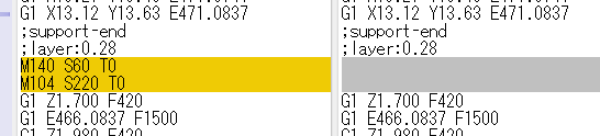
The temperature information is included in the layer where the model starts printing, including the brim.
However, pre-extrusion and raft are not included in this target, and the printer head temperature and platform temperature are applied.
Since the place where the temperature setting is applied was the same in Ver4.6, this is probably the specification of FlashPrint.
In Simplify3D, rafts etc. were also subject to temperature setting, but from the viewpoint of preventing peeling from the platform, I think that the FlashPrint specifications are a problem.
First Layer Maximum Speed First Layer Maximum Travel Speed
The printing speed slows down by the specified layer from the second layer of the printing layer of the model part.
When the layer is specified on the left. The speed is unified to 30 mm / s or less.
Retraction-Extrude Speed, Extra Restart Length
The one on the left has the Extrude Speed increased, and the Extra Restart Length is specified as 1.0 mm.
The value of F is getting faster, and it is pushed out by the specified amount of correction.
Is it possible to eliminate the knocking sound by increasing the Retract Speed and decreasing the Extrude Speed?
Is the correction value a value to compensate for the fact that the resin is pulled out a little when moving after pulling back?
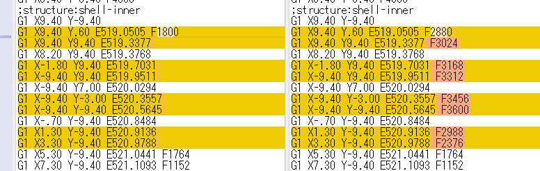
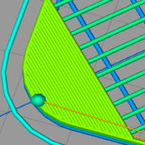
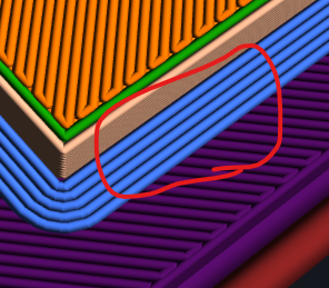
Visible Interior Max Speed Invisible Interior Max Speed
Both specify the speed of the printed part inside the outer frame.
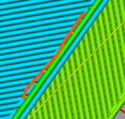
The red line part in the image above.
“Visible” refers to the top layer, and “invisible” refers to layers other than the top layer.
First, when the parameter of the invisible layer is 30 mm / s and the speed during resin extrusion is 60 mm / s.
The one on the right specifies the parameters.
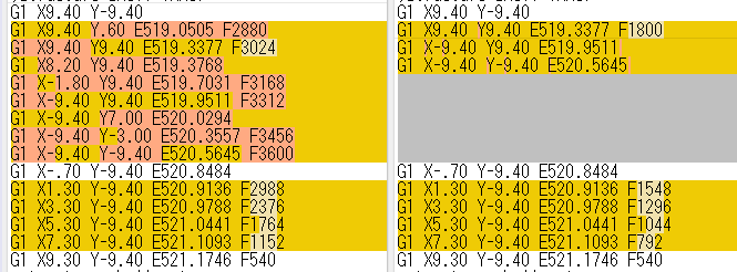
It can be seen that the maximum speed of the inner circumference of the middle layer is suppressed to F1800 (30 mm / s).
Also, although it has nothing to do with this parameter, if you look at the left side, you can see that the speed is adjusted with F3600 (60mm / s) as the maximum.
Regarding the frame (outline), it can be seen that the speed is adjusted according to the gravity on the 3D printer side.
The speed of the top layer is also controlled by the parameter of “visible internal maximum speed”.
The printing order of the layers is the inner circumference (inside the outer frame), the outer circumference (outside the outer frame), and the filling (filling part inside the model), but when printing the inner circumference, the part that is combined with the others is the part. Since there is only the print (or platform) below, it may be used to prevent speeding up for proper fixation.
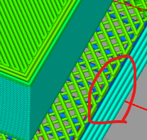
Infill Density Control
It seems that you can change the infill density by specifying the layer.
This is what I saw when the density of 20-40 layers was set to 50%.
The layer number is specified with the bottom of the model as 1. However, if that layer is not a packed layer, it will consist of the next layer.
Middle Layers-Path Width, Fill Density
The operation of the parameters is the same as that of the lower layer.
The help was exactly the same.
Does it mean a buffer to connect the bottom layer and the top layer, or to improve the quality of the top layer?
By tuning the parameters of the middle layer and the top layer, it may be possible to balance speed and quality improvement of the bottom of the model.
Top Layers-Path Width
When the path width of the top layer was changed from 0.4 to 0.2, it became as follows.
I think that the path width of the top layer is a parameter for improving the quality of the bottom of the model.
Generate Brim Inside Holes
As stated in the help, if there is a brim inside a hole etc., it may be troublesome to remove it, so I think that I introduced this parameter.
If “yes”.
If “No”.

I think it would have been better not to attach a filter by area or only when it was completely filled.
It’s difficult to remove small holes when removing the brim, but I think it’s easy to remove if there is a certain size.
Well, it doesn’t start to peel off from the inside, so maybe it’s okay.
Back Fan Speed
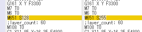
The value of M651 changes according to the ratio.
255 is 100%.
Not sure if this setting is alive in Adventurer3.
The chassis fan turns around immediately after the device is turned on, and I tried changing the parameters in the test, but it didn’t feel like it had changed.
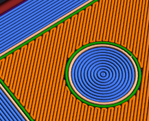
Ironing
The following results are obtained when turned on.
The preview is done in Simplify3D. Unfortunately, it is not displayed in the FlashPrint preview.

After outputting the top layer, discharge data is created so that the discharge ratio is 0.0934579 at the same height as the top layer.
Looking at this ratio, I think that the output is 0.04 mm wide (probably 1/10 of the path width).
The area to be filled is inside the first round of the outer frame.
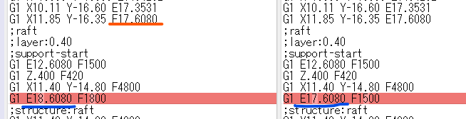
Z Offset
What was said in How to adjust height calibration and global Gcode offset amount was also implemented in FlashPrint.
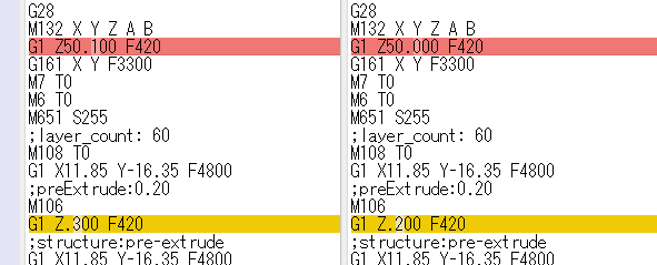
The offset with 0.1 (left).
Z is output incremented by the specified offset.
However, I don’t think it makes much sense to keep it as a parameter of this designated slicer body.
In the case of Adventurer3, the head is configured using paper, but the offset amount is determined at the output stage, assuming the actual gap due to the degree of paper catching during calibration and expansion due to bed temperature.
I think it is better to output 0.0 on the slicer side and determine the offset amount before transferring to the 3D device side.
If it is FlashPrint, it would be nice if it could be set on the multi-device control screen and the Z-axis value was changed when sending the G code.
There is no description in the help and no tooltip help is displayed, so I wonder if I hurriedly put it in at the very end.
A little noticed
- The setting range of the “Advanced”-“First Layer Extrusion Rate” parameter was different between 4.6 and 5.1.
4.6 is 80-200, 5.1 is 50-200. - Brim occurrence position
It seems that the output is based on the bottom of the model.
Simplyfy3D is designed to be generated directly above the platform (first layer).
Perhaps it’s due to the difference between controlling the resistance to peeling from the platform and controlling the resistance to peeling from the model.
Is it a difference in thinking?
コメント