
In the calibration of Adventurer3, it seems that it can be calibrated only in units of 0.1 mm on the Z axis (I do not know the unit, I think that there was a statement in Twitter of the FlashForge agency that it is a point instead of mm), so calibrate Depending on the state of the gap at the time, the gap may be too large, or conversely, the gap may be small.
If there are many gaps, it will not be firmly fixed to the bed or it will come off in the middle, and if there are few gaps, the first layer will be thin, the filament will not be pushed out in the required amount, a canning sound will be heard, and the brim will stick to the bed. It may not come off.
In Simplify3D, the output parameter can make the first layer lower than the other layers, but depending on the situation at the time of calibration, it seems better to correct with the actual value instead of the ratio.
Global Gcode
In Simplify3D, there is a global GCode offset in the GCode set in FFF, and you can apply an offset to each of the XYZ of the output GCode data.
When measuring the gap between the nozzle and the paper during calibration, the amount of the gap is felt by the resistance between the paper and the nozzle, and the Z coordinate of the global GCode is offset accordingly to output the first layer.
Adjustment method
Calibrate
After starting Adventurer3, calibrate.
Personally, I am in the following state.
- Insert the paper between the nozzle and the bed and insert it.
- When I move the paper, I feel that it is caught between the nozzle and the paper (there is resistance).
At the very least, it is possible to prevent the paper from being inserted, but sometimes, even if the paper is moved, it does not feel stuck and may be squishy. The offset amount is adjusted according to the state of catching.
Offset amount adjustment
If there is a catch
It seems that the gap with the nozzle is slightly less than the thickness of the paper.
Adjust the Z-axis offset amount to -0.04 to -0.07.
If there is no catch
Since the gap with the nozzle is larger than the thickness of the paper, it seems that the gap is about 0.1 mm, so adjust it to about -0.07 to -0.09. If true, maybe it should be lowered by -0.1 further at the time of calibration.
result
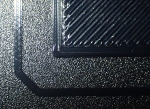
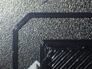
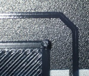
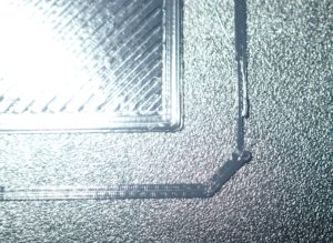
By making this adjustment, the first layer can also be output without any particular problem.
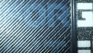
The following is the output result of the first layer when a 7 cm x 7 cm square is output.
Finally
It’s a hassle to make corrections, but I have to proofread each time, so I wonder if this can be helped.
コメント